Material Data in DEFORM
Lecture 3 · Modelling and Simulation of Processes I – Forming (MSPO2_6I)
Winter semester 2026/2027
Materiálovotechnologická fakulta · STU Bratislava
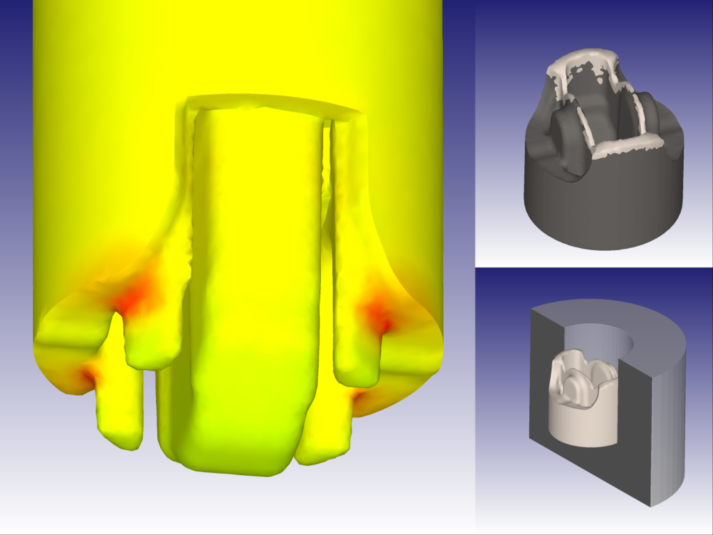
Piston forging – punch and workpiece in DEFORM (© SFTC)
Today's agenda (120 min, no break)
| Time | Block | Content |
|---|---|---|
| 0 – 10 | 1 · Why it matters | Garbage in, garbage out — one part, two flow curves |
| 10 – 20 | 2 · Material window | Layout, library, Regular vs Mixture, units |
| 20 – 30 | 3 · Elastic data | E, ν, α(T), hyperelastic materials |
| 30 – 60 | 4 · Flow stress | Testing, tables, power law, Johnson–Cook, Zerilli–Armstrong, sinh-Arrhenius, choosing a model |
| 60 – 80 | 5 · Yield & hardening | von Mises, Hill 48, R-values, Barlat; isotropic, kinematic, Yoshida–Uemori |
| 80 – 90 | 6 · Creep | Creep curve, DEFORM creep models, relaxation |
| 90 – 105 | 7 · Thermal data | k, heat capacity, emissivity, density, interface HTC |
| 105 – 115 | 8 · Beyond mechanics | Grain (JMAK), phases, hardness, diffusion, EM, fracture |
| 115 – 120 | 9 · Wrap-up | Checklist per process, quiz |
The DEFORM Material window

Material window, Elastic tab — copper C10100 (DEFORM-3D)
- Material list — all materials of the project; each object points to one
- Regular / Mixture — single phase or several phases
- Phase — Add, Remove, Transformation, Grain
- Tabs: Plastic · Elastic · Thermal · Diffusion · Dislocation · Hardness · Elec./Mag. · Advanced · Texture
- Buttons: New, Delete, Load from lib, Save in lib, Import, Export, Copy prop., Unit conv.
- Each property: Constant or f(Temp), edited in a table (pencil icon)
Material library: load, save, import, export
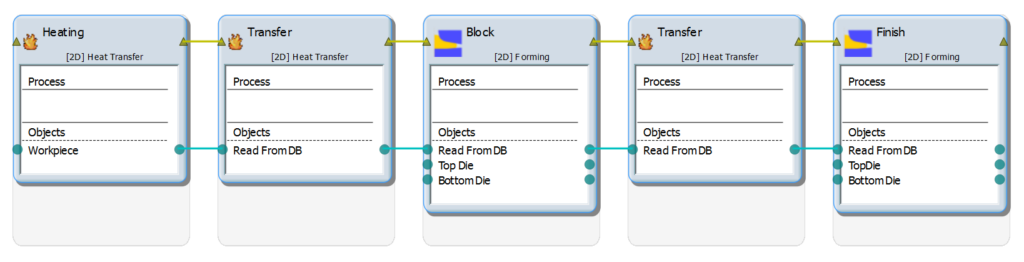
Multiple operations — heating, forging, trimming: one material, many temperatures (© SFTC)
Regular material or Mixture of phases?
| Regular | Mixture | |
|---|---|---|
| Phases | one | 2 … n (austenite, ferrite, pearlite, bainite, martensite …) |
| Data | one set per tab | one set per phase + transformation data |
| Use | forming, machining | heat treatment, quenching, carburising |
- \(\xi_i\) volume fraction of phase \(i\), \(P_i\) its property (σ̄, k, E …)
- Transformation button: kinetics (diffusion / martensite), latent heat, volume change, TRIP
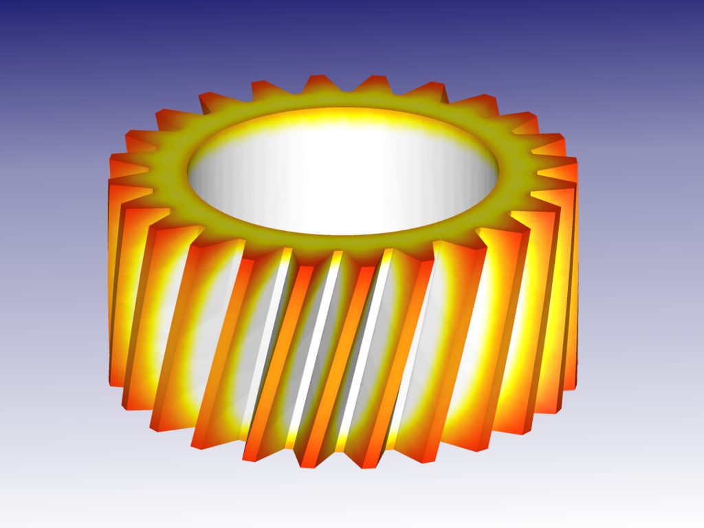
Carburised and quenched helical gear — martensite fraction (© SFTC)
Units: the C10100 trap — and which tabs you need
| Quantity | English (C10100 above) | SI in DEFORM |
|---|---|---|
| E | 16 679 ksi | 115 000 MPa |
| α | 9.44·10⁻⁶ /°F | 1.7·10⁻⁵ /°C |
| Tref | 68 °F | 20 °C |
| Stress | ksi | MPa = N/mm² |
| k | Btu/(s·in·°F) | N/(s·°C) = W/(m·K) |
| ρ·cp | Btu/(in³·°F) | N/(mm²·°C) = MJ/(m³·K) |
| ρ | lb/in³ | t/mm³ (7.7·10⁻⁹ for steel) |
Unit system is set per problem; mixing an English library entry into an SI problem → use Unit conv.
| Simulation | Plastic | Elastic | Thermal | Phase / grain |
|---|---|---|---|---|
| Isothermal forging | ● | – | – | – |
| Hot / warm forging | ● | – | ● | ○ |
| Springback, residual σ | ● | ● | ○ | – |
| Die stress (elastic die) | – | ● | ○ | – |
| Heat treatment | ● | ● | ● | ● |
| Induction heating | ○ | ○ | ● | ● + EM |
● required ○ recommended – not used
When does DEFORM need elastic data?
- Rigid-plastic object: elastic strain neglected → no E, ν needed (most forging)
- Elastic object: dies, die inserts, shrink rings → E, ν, α
- Elasto-plastic object: springback, residual stress, distortion, heat treatment
elastic + plastic + thermal + transformation strain

Elastic range: strain recovers fully on unloading
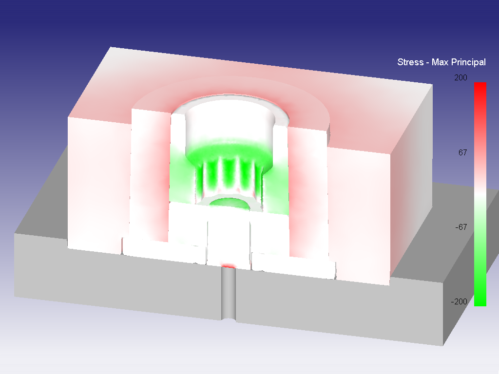
Die stress analysis with elastic dies (© SFTC)
E(T) and thermal expansion α(T)
E(T) of carbon steel — EN 1993-1-2 reduction factor kE

α(T) of several steels in DEFORM (course lecture)
- E of steel falls to about 1/3 at 600 °C and almost zero above 1000 °C — use f(Temp) for quenching and hot die stress
- α is the secant value from Tref; austenite expands more than ferrite (≈ 2.2 vs 1.4·10⁻⁵ /K)
Flow stress: \( \bar\sigma = f(\bar\varepsilon,\ \dot{\bar\varepsilon},\ T) \)

Engineering vs true curve

Permanent strain after the yield point
- Flow stress = true stress needed to keep plastic flow going
- Depends on strain (hardening), strain rate and temperature; also on prior history
- Rigid-plastic FEM uses only the plastic part — the curve starts at the yield stress
- Engineering values are valid only up to necking (uniform elongation)
Temperature softens, strain rate strengthens

Stress–strain curves vs temperature and strain rate (course lecture)
| Regime | T / Tm | Dominant effect |
|---|---|---|
| Cold | < 0.3 | Strain hardening, weak rate effect (m ≈ 0–0.05) |
| Warm | 0.3 – 0.5 | Both, recovery starts |
| Hot | > 0.5 – 0.6 | Rate + T; hardening balanced by recovery / DRX (m ≈ 0.1–0.2) |
- Strain-rate sensitivity \( m = \partial\ln\bar\sigma/\partial\ln\dot{\bar\varepsilon} \)
- Superplastic alloys: m ≥ 0.3–0.5
- Adiabatic heating: \( \Delta T \approx \dfrac{\beta\int\bar\sigma\,d\bar\varepsilon}{\rho\,c_p} \), β ≈ 0.9
Where flow curves come from
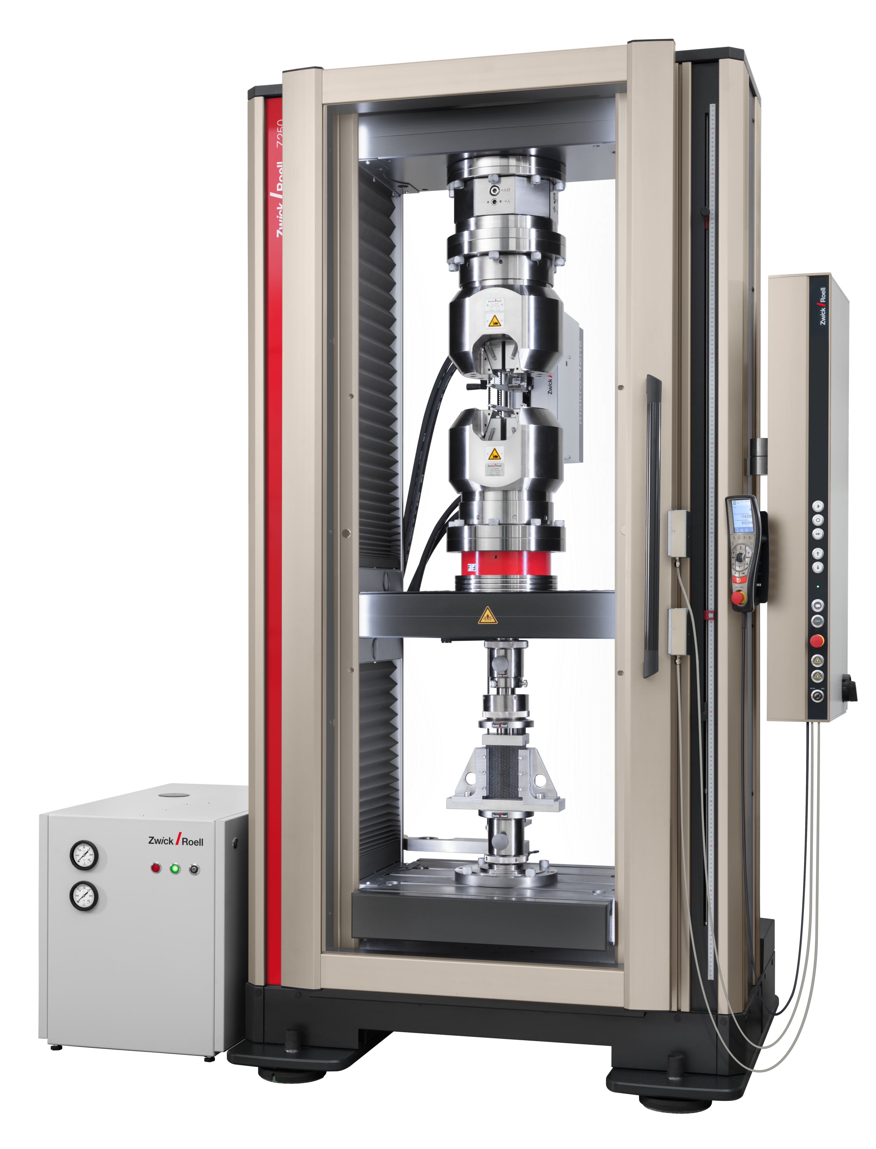
Tensile test
ε < 0.2–0.3, ε̇ ≈ 10⁻³–10⁻¹ s⁻¹ (© ZwickRoell)

Compression (upsetting)
ε ≤ 1, friction correction

Gleeble hot compression
up to ≈ 1700 °C, ε̇ to 10² s⁻¹ (© DSI)
Split Hopkinson bar (SHPB)
ε̇ ≈ 10²–10⁴ s⁻¹
| Test | Strength | Limitation | DEFORM use |
|---|---|---|---|
| Tension | Standard, simple stress state | Necking limits strain | Sheet, cold forming start of curve |
| Compression / plane strain | Large strains, hot | Friction, barrelling → inverse correction | Bulk forming, forging |
| Torsion | Very large strains (ε > 5) | Gradient through radius | Hot rolling, DRX |
| SHPB | High rates | Small strain, adiabatic | Machining, impact (J–C) |
Tabular flow stress \( \bar\sigma(\bar\varepsilon, \dot{\bar\varepsilon}, T) \) and interpolation

DEFORM flow-stress table: curves per T and ε̇ (course lecture)
Value at ε̇ = 50 s⁻¹ from the same four table points: 1012 vs 1028 MPa
- Table = curves for several T × ε̇, each sampled in ε̄ — the most common format in DEFORM libraries
- Between points DEFORM interpolates; strain rate spans decades → logarithmic interpolation in ε̇ is the physically sensible choice
- Typical table: 5–8 temperatures, 4–6 strain rates (10⁻² … 10² s⁻¹), strains 0 … 2
Where Z and the sinh law are used
| Operation | Use of Z / sinh law |
|---|---|
| Hot closed-die forging | Flow stress for die fill and load; Z → DRX grain size in the part |
| Hot rolling, pass schedules | Mean flow stress per pass; Z → recrystallisation between passes |
| Aluminium extrusion | Sinh law is the classic model (Sheppard & Wright); exit temperature and speed limits |
| Isothermal / hot-die forging of Ti, Ni alloys | Low ε̇, near-creep regime; m from the sinh law |
| Process design and scale-up | Equal Z: transfer Gleeble results to the press |
| Processing maps | Choose safe T–ε̇ windows (DRX, no shear bands) |
| Creep of dies and hot tools | Same Arrhenius structure, low-stress (power-law) branch |
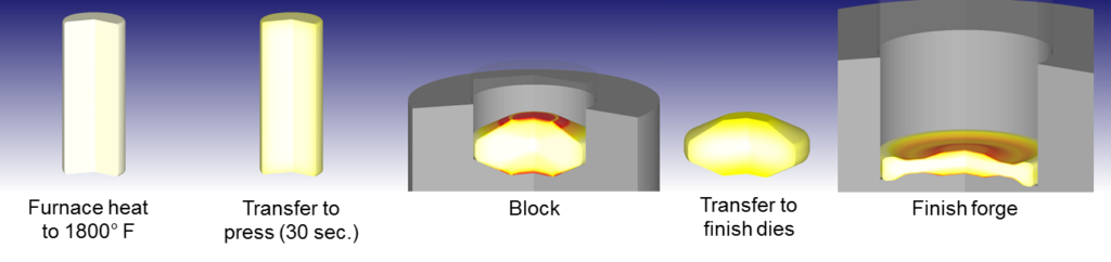
Hot forging sequence of a disc (© SFTC)

Ring rolling — Z changes along the roll gap (© SFTC)
Microstructure-based, AI and user-defined flow stress

Flow-stress options in the Plastic tab (course lecture)
| Option | Idea | When |
|---|---|---|
| Dislocation density | σ̄ = σ₀ + αMGb√ρ; ρ evolves with ε, ε̇, T | Multi-step hot forging, DRX |
| Texture / crystal plasticity | Grain orientations → anisotropic flow | Ti, Mg, sheet, earing |
| DNN predictor | Neural network: chemistry → flow curve | No test data, early design |
| User routine | Own FORTRAN subroutine compiled into the solver | Research models |
| Conversion | Equation → table; test data → fitted model | Library building |
The Material Suite (SFTC) fits flow stress from compression data, computes TTT diagrams from composition and JMAK constants.
Match the model to the process
Decision guide used in this course
From the stress tensor to one number: effective stress

Nine stress components on a volume element (course lecture)
- Hydrostatic part \(\sigma_m\) does not cause yielding of dense metals
- Flow curve (uniaxial) is compared with \(\bar\sigma\) → yield when \(\bar\sigma = \sigma_f(\bar\varepsilon, \dot{\bar\varepsilon}, T)\)
- The yield function defines how \(\bar\sigma\) is computed — Plastic tab, “Yield function type”
von Mises vs Tresca — isotropic yield criteria
Plane-stress yield loci (σ₃ = 0)
- Max. difference: 15.5 % in pure shear (\(k = \sigma_0/\sqrt3\) vs \(\sigma_0/2\))
- Experiments on most metals lie closer to von Mises
- von Mises is smooth → convenient for FEM; DEFORM default

Yield function types in DEFORM (course lecture)
Hill 1948 — orthotropic anisotropy
- 6 constants F, G, H, L, M, N; axes = rolling (x), transverse (y), normal (z)
- F = G = H = 1/(2σ₀²), L = M = N = 3/(2σ₀²) → von Mises
- DEFORM: enter FGHLMN directly or R-values (next slide)

Hill quadratic (FGHLMN) dialog in DEFORM (course lecture)
Isotropic hardening — the yield surface expands

Work hardening: reloading needs a higher stress (course lecture)
Isotropic (left) and kinematic (right) hardening in the deviatoric plane
- Default in DEFORM; exact for monotonic loading (most forging)
Kinematic hardening — the yield surface translates
Load reversal after 5 % strain: σ₀ = 300 MPa, linear hardening
Armstrong–Frederick: \( \dot{\boldsymbol\alpha} = c\,\dot{\boldsymbol\varepsilon}^{p} - \gamma\,\boldsymbol\alpha\,\dot{\bar\varepsilon}^{p} \)
- Bauschinger effect: after tension the material yields earlier in compression
- Matters for bending–unbending over die radii and drawbeads, cyclic loading
- Mixed hardening: fraction isotropic + fraction kinematic
- Data: tension–compression or cyclic shear tests

Hardening rule selection (course lecture)
Yoshida–Uemori two-surface model and springback
- Two surfaces: inner yield surface moves inside a bounding surface
- Captures: early re-yielding, transient Bauschinger, permanent softening, work-hardening stagnation
- Plus E-modulus degradation with plastic strain: \( E = E_0 - (E_0 - E_a)\,[1 - e^{-\xi\bar\varepsilon^p}] \)
- 7 material constants (Y, C, B, Rsat, b, m, h) from cyclic tension–compression tests
- Standard for AHSS springback (DP, TRIP, CP steels)
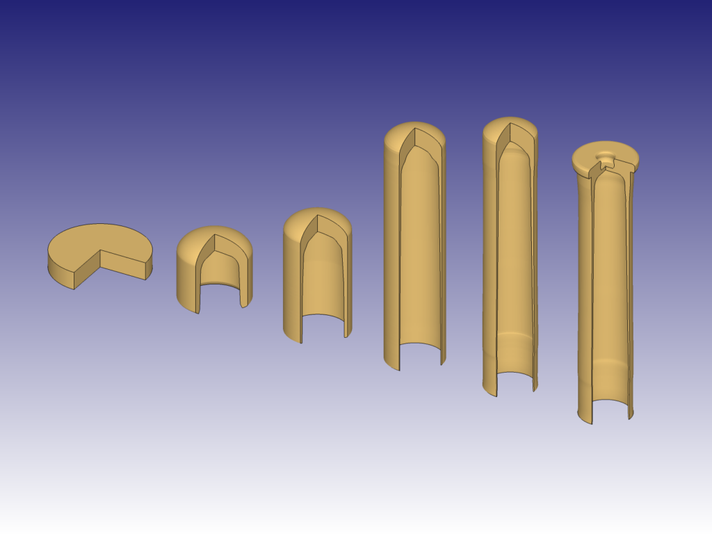
Multi-stage drawing of a casing — unloading after each stage (© SFTC)
Creep: plastic flow at constant stress over time
Creep curves for three stress levels (schematic, computed)

Stages I, II, III (course lecture)

Creep option in the Plastic tab (course lecture)
- Significant above ≈ 0.4 Tm; strain grows at constant load — I primary, II steady (minimum rate), III tertiary → rupture
- In DEFORM creep is added to the elasto-plastic strain: \( \dot{\boldsymbol\varepsilon} = \dot{\boldsymbol\varepsilon}^{e} + \dot{\boldsymbol\varepsilon}^{p} + \dot{\boldsymbol\varepsilon}^{c} + \dot{\boldsymbol\varepsilon}^{th} \)
Creep models available in DEFORM
| Model | Equation | Typical use |
|---|---|---|
| Power law (Norton) | \( \dot\varepsilon^{c} = A\,\bar\sigma^{n} \) | Steady-state creep, relaxation |
| Bailey–Norton | \( \varepsilon^{c} = A\,\bar\sigma^{n}\,t^{m} \) (m < 1) | Primary + secondary creep |
| Perzyna | \( \dot\varepsilon^{c} = \gamma\left\langle \dfrac{\bar\sigma}{\sigma_y} - 1\right\rangle^{p} \) | Viscoplasticity above yield |
| Soderberg | \( \dot\varepsilon^{c} = A\left[\exp(\bar\sigma/\sigma_0) - 1\right] \) | Low-stress creep |
| Exponential | \( \dot\varepsilon^{c} = A\,e^{B\bar\sigma}\,e^{-Q/RT} \) | High-stress creep, T-dependent |
| Tabular | \( \dot\varepsilon^{c} = f(\bar\sigma, T, \varepsilon^{c}) \) | Measured data |
- Norton exponent n: 3–8 for dislocation creep; ≈ 1 for diffusion creep
- Fit constants to the stress and temperature range of the process — creep data extrapolate even worse than flow stress
Where creep shows up in forming
Stress relaxation under fixed strain, Norton n = 5 (computed)
- Stress relaxation: shrink-fit die rings and bolts at temperature lose preload
- Isothermal / hot-die forging of Ti and Ni alloys at low ε̇ (10⁻³–10⁻² s⁻¹)
- Superplastic forming of Ti-6Al-4V, Al 5083 (m ≥ 0.5)
- Hot sizing, stress-relief annealing: residual stress drops during holding
- Heat treatment: creep during slow cooling and tempering

Dead-weight creep frame (© DoITPoMS, Univ. of Cambridge)
The Thermal tab

Thermal tab: conductivity, heat capacity / specific heat, emissivity, density (course lecture)
| Property | SI unit in DEFORM | Controls |
|---|---|---|
| Conductivity k(T) | N/(s·°C) = W/(m·K) | Heat flow inside the part |
| Heat capacity ρcp(T) | N/(mm²·°C) | Heating per unit energy |
| Emissivity ε | – | Radiation to environment |
| Density ρ | t/mm³ | Mass (hammers), specific-heat option |
Emissivity and density
| Surface | Emissivity ε |
|---|---|
| Oxidised / scaled steel, hot | 0.7 – 0.9 |
| Bright machined steel | 0.2 – 0.4 |
| Polished aluminium | 0.04 – 0.1 |
| Oxidised titanium | 0.5 – 0.7 |
- At 1200 °C radiation dominates heat loss in transfer from furnace to press
- Density: mass for hammers and screw presses, specific-heat option, volume change ρ(T) in heat treatment

Open-die cogging of a hot ingot: hours of radiation cooling between passes (© SFTC)
Die–workpiece heat transfer and the Inverse HTC module

1 · Test with thermocouples

2 · Simulated vs measured T(t)

3 · Fitted HTC (© SFTC)
- Not a material property — set in Inter-object, but sits next to k in every heat balance
- DEFORM defaults: forming contact ≈ 11 N/(s·mm·°C) (= 11 kW/(m²·K)), free surface convection ≈ 0.02
- Inverse HTC: DEFORM varies h(t) or h(T) until simulated thermocouple curves match the measured ones
- Same idea used for flow stress: inverse analysis of the compression test
Recrystallisation and grain size: JMAK (Avrami)
Static recrystallisation, Avrami n = 1.5, t0.5 from 0.1 s to 40 s (illustrative)
- DRX starts at \(\varepsilon_c \approx 0.8\,\varepsilon_p\)
- Data: Phase → Grain button
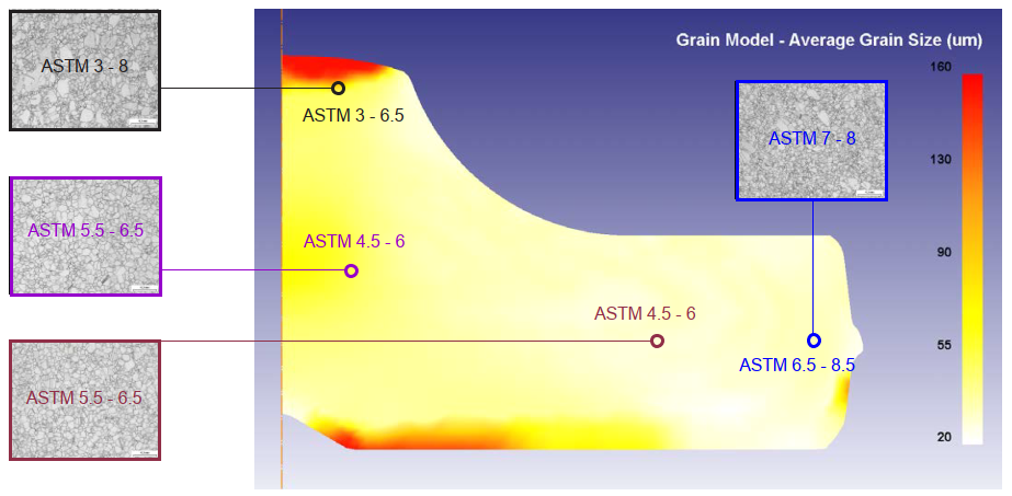
Grain size in a forged Waspaloy disc (© SFTC)
Phase transformation kinetics and hardness
Diffusional (ferrite, pearlite, bainite)
Martensite — Koistinen–Marburger
Hardness — Hardness tab
- TTT / CCT from tests or from composition (Material Suite, JMatPro)
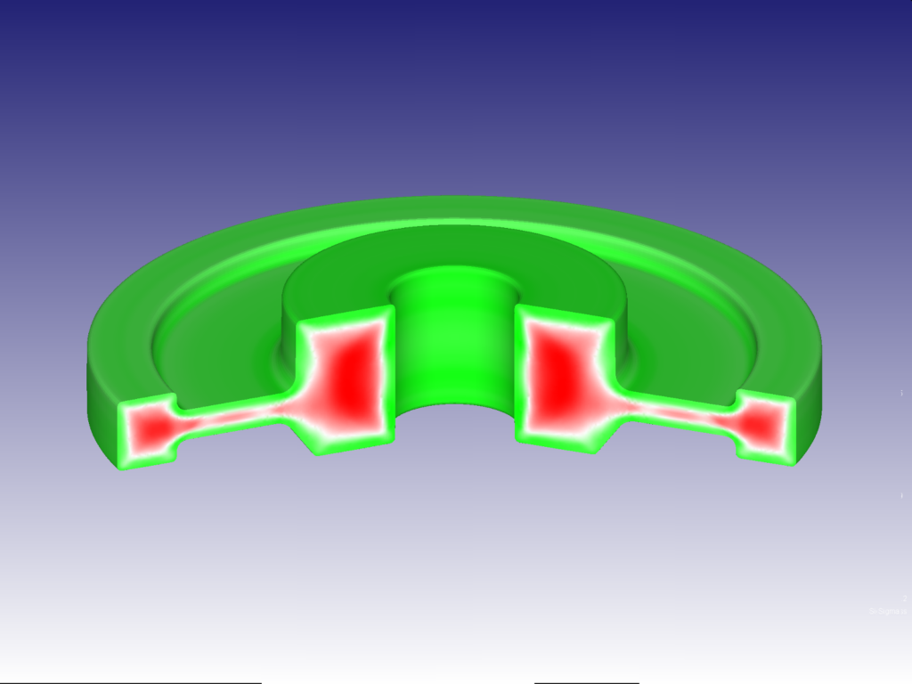
Residual hoop stress after quenching a disc (© SFTC)
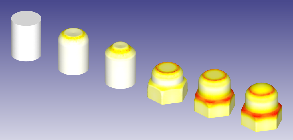
Cold heading progression — hardness from strain hardening (© SFTC)
Diffusion (carburising) and electro-magnetic data (induction)
Diffusion tab
- Carbon in austenite: D₀ ≈ 2.3·10⁻⁵ m²/s, Q ≈ 148 kJ/mol
- Surface: carbon potential + mass-transfer coefficient
- Carbon content → Ms, hardness, TTT shift
Elec./Mag. tab
- Electrical resistivity ρe(T)
- Relative magnetic permeability μr(T, H) — drops to 1 above Curie point (≈ 770 °C)
- Above Curie: δ grows ≈ 10× → heating zone moves inward
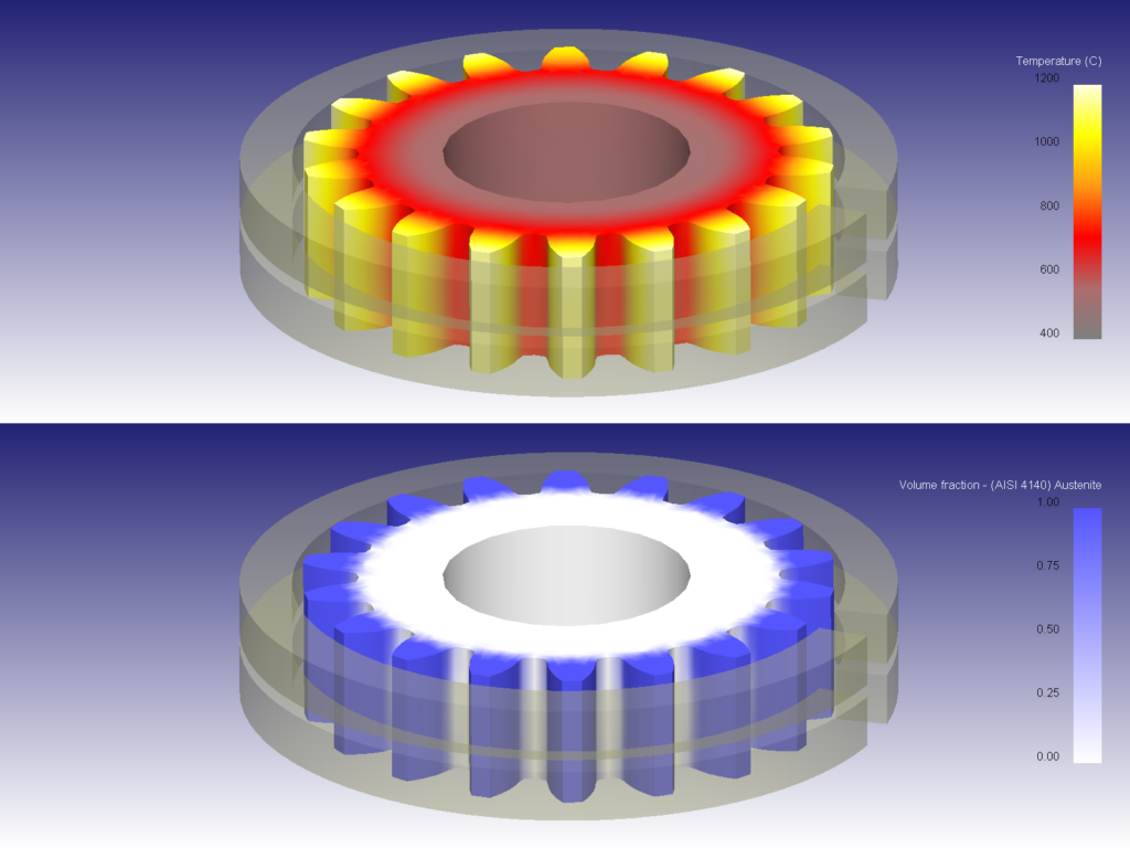
Induction-hardened spur gear (© SFTC)
Ductile fracture: normalised Cockcroft–Latham
- Only tensile max. principal stress counts — compression does no damage
- C is a material constant, calibrated by simulating a test to its crack strain
- Typical C: 0.2 – 0.6 (cold steels) — depends on inclusions, T
- Advanced tab: damage model choice, element deletion threshold
- Others in DEFORM: Oyane, Rice–Tracey, Brozzo, McClintock, Lemaitre …
Upsetting: tensile hoop stress at the bulge
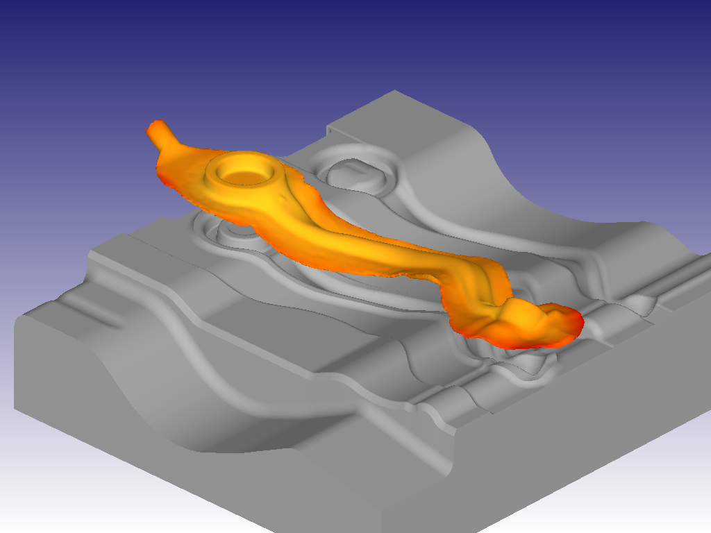
Cross-wedge rolling — risk of central cavity (Mannesmann effect) (© SFTC)
Checklist: which material data does my simulation need?
| Process | Flow stress | Yield / hardening | Elastic | Thermal | Extra |
|---|---|---|---|---|---|
| Cold forging, heading | Power law / table, ε to 2–3 | von Mises, isotropic | For die stress | k, ρcp (heating) | Damage C |
| Hot closed-die forging | Table σ(ε, ε̇, T) or sinh | von Mises, isotropic | – | k(T), ρcp(T), ε, HTC | Grain (JMAK) |
| Machining | Johnson–Cook / ZA | von Mises | Tool | k, ρcp | Damage, wear |
| Sheet / springback | Swift / Hollomon | Hill 48 / Barlat, kinematic, Y-U | E(ε̄p) | – | FLD |
| Heat treatment | Per phase, f(T) | Isotropic (+ TRIP) | E(T), α(T) | Per phase | TTT, latent heat, ΔV, HV |
| Induction hardening | Per phase | Isotropic | E(T), α(T) | k, ρcp | ρe(T), μr(T) |
- Check units (SI / English) · 2. Check validity range vs process · 3. Check temperature dependence · 4. Validate one result (force, T) against a measurement
Quick quiz & sources
- Write the general flow-stress function and name its three variables. σ̄ = f(ε̄, ε̇̄, T): effective plastic strain, effective strain rate and temperature.
- Why can a rigid-plastic forging simulation run without E and ν? In bulk forming the plastic strains (hundreds of %) dwarf the elastic ones (fractions of a %), so the rigid-plastic formulation neglects elasticity. E and ν are needed only for elastic dies, springback / residual stresses and heat treatment.
- Which flow-stress model for machining, which for hot forging — and why? Machining: Johnson–Cook (or Zerilli–Armstrong) – very high strain rates and adiabatic heating. Hot forging: a measured table σ(ε, ε̇, T) or the sinh-Arrhenius law – thermally activated flow where T and ε̇ interact.
- What happens if the process exceeds the strain-rate range of a table? DEFORM extrapolates without a warning – it holds the last value or extends the last slope – so the flow stress there is a guess (e.g. a table to 10 s⁻¹ used at 10⁴ s⁻¹ is ≈ 8 % too low). Compare max ε, ε̇, T from the post-processor with the table range.
- How do R-values enter the Hill 48 criterion? What does Δr predict? R-values at 0°, 45° and 90° set the ratios of Hill's constants (H/G = r₀, H/F = r₀/r₉₀, …). Δr = (r₀ − 2r₄₅ + r₉₀)/2 predicts earing of drawn cups: Δr > 0 → ears at 0° and 90°, Δr < 0 → ears at 45°.
- Isotropic vs kinematic hardening: what happens to the yield surface? Isotropic: the yield surface grows uniformly around a fixed centre (radius = current flow stress). Kinematic: it keeps its size and moves by the back stress α → early reverse yielding (Bauschinger effect), important for springback.
- Heat capacity vs specific heat — what does DEFORM expect in SI units? Heat capacity is per volume (ρ·cp), specific heat per mass. DEFORM's default field expects heat capacity: steel ≈ 7850 kg/m³ × 440 J/(kg·K) ≈ 3.45 N/(mm²·°C) = 3.45 MJ/(m³·K). Typing 460 there makes the billet practically never heat up.
- How is the Cockcroft–Latham constant C obtained? By calibration: simulate a test (upsetting, tension, notched bar) to the strain at which the real specimen cracked; the damage D at the crack site at that moment is C. It depends on the heat of material, cleanliness and temperature.
- SFTC: DEFORM V14 manual, Ch. 10 Material Data; Material Suite; deform.com
- Necpal, M.; Sobota, R.: Modelovanie a simulácia procesov tvárnenia. STU, 2023
- Kobayashi, Oh, Altan: Metal Forming and the FEM. 1989
- Johnson & Cook (1983); Jaspers & Dautzenberg, J. Mater. Process. Technol. 122 (2002)
- Zerilli & Armstrong, J. Appl. Phys. 61 (1987)
- Sellars & Tegart (1966) — sinh law; Hill (1948); Barlat & Lian (1989), Barlat et al. (1991)
- Yoshida & Uemori, Int. J. Plasticity 18 (2002)
- EN 1993-1-2: thermal and mechanical properties of steel
- Images © SFTC, Gleeble/DSI, ZwickRoell, DoITPoMS — linked for teaching
Next lecture: preprocessing — mesh, boundary conditions, friction